BulldozerD11 (talk | contribs) (Imported from Wikipedia - defines term) |
Tag: Visual edit |
||
| Line 4: | Line 4: | ||
== History == |
== History == |
||
| − | [[File:Universal Shaft.ogv|thumbnail|This video shows different parts and operation of Universal Shaft.]] |
+ | [[File:Universal Shaft.ogv|thumbnail|This video shows different parts and operation of Universal Shaft.|link=Special:FilePath/Universal_Shaft.ogv]] |
The main concept of the universal joint is based on the design of [[gimbal]]s, which have been in use since antiquity. One anticipation of the universal joint was its use by the Ancient Greeks on [[ballistae]]{{Cn|date=February 2013}}. The first person known to have suggested its use for transmitting motive power was [[Gerolamo Cardano]], an Italian mathematician, in 1545, although it is unclear whether he produced a working model. In Europe, the device is often called the ''Cardan joint'' or ''Cardan shaft''. [[Christopher Polhem]] of Sweden later reinvented it, giving rise to the name ''Polhemsknut'' in Swedish. |
The main concept of the universal joint is based on the design of [[gimbal]]s, which have been in use since antiquity. One anticipation of the universal joint was its use by the Ancient Greeks on [[ballistae]]{{Cn|date=February 2013}}. The first person known to have suggested its use for transmitting motive power was [[Gerolamo Cardano]], an Italian mathematician, in 1545, although it is unclear whether he produced a working model. In Europe, the device is often called the ''Cardan joint'' or ''Cardan shaft''. [[Christopher Polhem]] of Sweden later reinvented it, giving rise to the name ''Polhemsknut'' in Swedish. |
||
| Line 104: | Line 104: | ||
==See also == |
==See also == |
||
| + | * Twin Spring Coupling |
||
| − | * |
+ | *[[Cardan shaft]] |
* [[Constant-velocity joint]] |
* [[Constant-velocity joint]] |
||
* [[Elastic coupling]] |
* [[Elastic coupling]] |
||
Revision as of 18:09, 1 February 2021
A universal joint
A universal joint, universal coupling, U-joint, Cardan joint, Hardy-Spicer joint, or Hooke's joint is a joint or coupling in a rigid rod that allows the rod to 'bend' in any direction, and is commonly used in shafts that transmit rotary motion. It consists of a pair of hinges located close together, oriented at 90° to each other, connected by a cross shaft.
History
This video shows different parts and operation of Universal Shaft.
The main concept of the universal joint is based on the design of gimbals, which have been in use since antiquity. One anticipation of the universal joint was its use by the Ancient Greeks on ballistae[citation needed]. The first person known to have suggested its use for transmitting motive power was Gerolamo Cardano, an Italian mathematician, in 1545, although it is unclear whether he produced a working model. In Europe, the device is often called the Cardan joint or Cardan shaft. Christopher Polhem of Sweden later reinvented it, giving rise to the name Polhemsknut in Swedish.
The mechanism was later described in Technica curiosa sive mirabilia artis (1664) by Gaspar Schott, who called it the paradoxum, but mistakenly claimed that it was a constant-velocity joint.[1] Shortly afterwards, between 1667 and 1675, Robert Hooke analysed the joint and found that its speed of rotation was nonuniform, but that this property could be used to track the motion of the shadow on the face of a sundial.[1] In fact, the component of the equation of time which accounts for the tilt of the equatorial plane relative to the ecliptic is entirely analogous to the mathematical description of the universal joint. The first recorded use of the term universal joint for this device was by Hooke in 1676, in his book Helioscopes.[2] He published a description in 1678,[3] resulting in the use of the term Hooke's joint in the English-speaking world. In 1683, Hooke proposed a solution to the nonuniform rotary speed of the universal joint: a pair of Hooke's joints 90° out of phase at either end of an intermediate shaft, an arrangement that is now known as a type of constant-velocity joint.
The term universal joint was used in the 18th century[3] and was in common use in the 19th century. Edmund Morewood's 1844 patent for a metal coating machine called for a universal joint, by that name, to accommodate small alignment errors between the engine and rolling mill shafts.[4] Lardner's 1877 Handbook described both simple and double universal joints, and noted that they were much used in the line shaft systems of cotton mills.[5] Jules Weisbach described the mathematics of the universal joint and double universal joint in his treatise on mechanics published in English in 1883.[6]
19th century uses of universal joints spanned a wide range of applications. Numerous universal joints were used to link the control shafts of the Northumberland telescope at Cambridge University in 1843.[7] Ephriam Shay's locomotive patent of 1881, for example, used double universal joints in the locomotive's drive shaft.[8] Charles Amidon used a much smaller universal joint in his bit-brace patented 1884.[9] Beauchamp Tower's spherical, rotary, high speed steam engine used an adaptation of the universal joint circa 1885.[10]
The term Cardan joint appears to be a latecomer to the English language. Many early uses in the 19th century appear in translations from French or are strongly influenced by French usage. Examples include an 1868 report on the Exposition Universelle of 1867[11] and an article on the dynamometer translated from French in 1881.[12]
Equation of motion
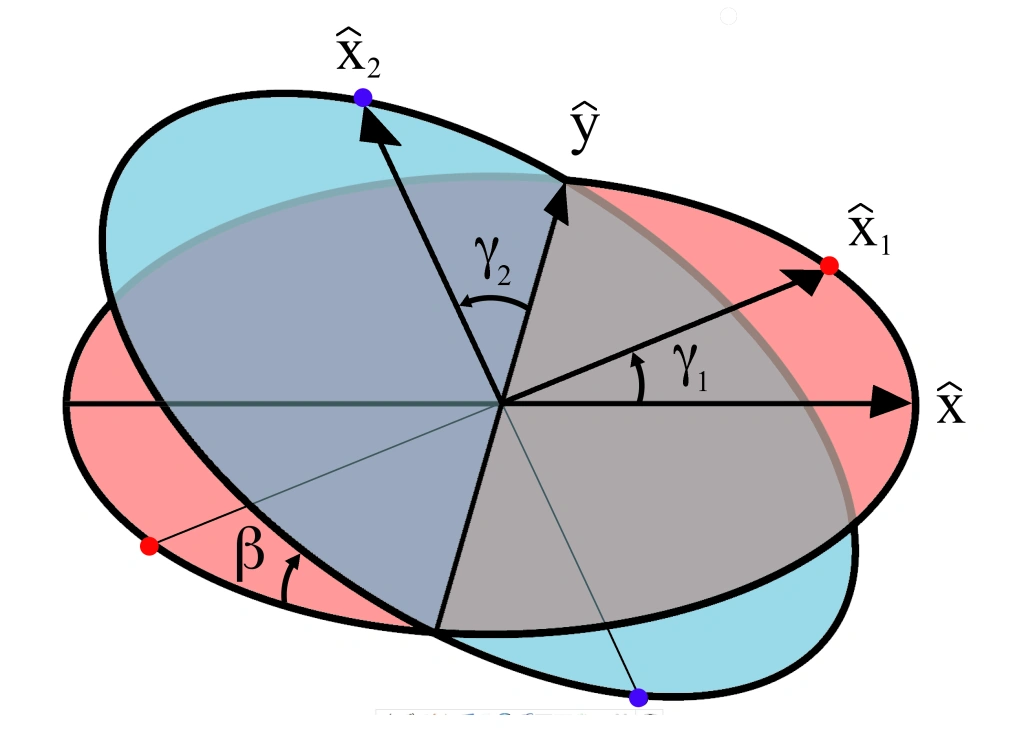
Diagram of variables for the universal joint. Axle 1 is perpendicular to the red plane and axle 2 is perpendicular to the blue plane at all times. These planes are at an angle β with respect to each other. The angular displacement (rotational position) of each axle is given by and respectively, which are the angles of the unit vectors and with respect to their initial positions along the x and y axes. The and vectors are fixed by the gimbal connecting the two axles and so are constrained to remain perpendicular to each other at all times.


The Cardan joint suffers from one major problem: even when the input drive shaft axle rotates at a constant speed, the output drive shaft axle rotates at a variable speed, thus causing vibration and wear. The variation in the speed of the driven shaft depends on the configuration of the joint, which is specified by three variables:
- The angle of rotation for axle 1
- The angle of rotation for axle 2
- The bend angle of the joint, or angle of the axles with respect to each other, with zero being parallel or straight through.

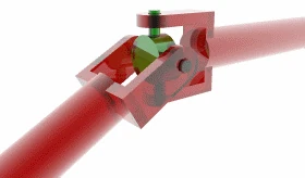
These variables are illustrated in the diagram on the right. Also shown are a set of fixed coordinate axes with unit vectors and and the planes of rotation of each axle. These planes of rotation are perpendicular to the axes of rotation and do not move as the axles rotate. The two axles are joined by a gimbal which is not shown. However, axle 1 attaches to the gimbal at the red points on the red plane of rotation in the diagram, and axle 2 attaches at the blue points on the blue plane. Coordinate systems fixed with respect to the rotating axles are defined as having their x-axis unit vectors ( and ) pointing from the origin towards one of the connection points. As shown in the diagram, is at angle with respect to its beginning position along the x axis and is at angle with respect to its beginning position along the y axis.


is confined to the "red plane" in the diagram and is related to by:
![{\displaystyle {\hat {\mathbf {x} }}_{1}=[\cos \gamma _{1}\,,\,\sin \gamma _{1}\,,\,0]}](https://services.fandom.com/mathoid-facade/v1/media/math/render/svg/23d0d0ee843932844bc8fe254ef3ea3be377b158)
is confined to the "blue plane" in the diagram and is the result of the unit vector on the x axis being rotated through Euler angles ]:
![{\displaystyle {\hat {x}}=[1,0,0]}](https://services.fandom.com/mathoid-facade/v1/media/math/render/svg/ba5514ef154e904d83a4db61f3cfffaf0e71090d)

![{\displaystyle {\hat {\mathbf {x} }}_{2}=[-\cos \beta \sin \gamma _{2}\,,\,\cos \gamma _{2}\,,\,\sin \beta \sin \gamma _{2}]}](https://services.fandom.com/mathoid-facade/v1/media/math/render/svg/906b4d2456dc89c2583605b0a70a14123c6edce1)
A constraint on the and vectors is that since they are fixed in the gimbal, they must remain at right angles to each other:

Thus the equation of motion relating the two angular positions is given by:

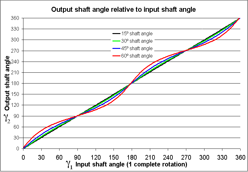
with a formal solution for :
![{\displaystyle \gamma _{2}=\tan ^{-1}[\tan \gamma _{1}/\cos \beta ]\,}](https://services.fandom.com/mathoid-facade/v1/media/math/render/svg/6ead36876354ae66891348a68293b680592ca87d)
The solution for is not unique since the arctangent function is multivalued, however it is required that the solution for be continuous over the angles of interest. For example, the following explicit solution using the atan2(y,x) function will be valid for :


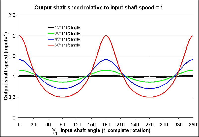
The angles and in a rotating joint will be functions of time. Differentiating the equation of motion with respect to time and using the equation of motion itself to eliminate a variable yields the relationship between the angular velocities and :


As shown in the plots, the angular velocities are not linearly related, but rather are periodic with a period twice that of the rotating shafts. The angular velocity equation can again be differentiated to get the relation between the angular accelerations and :


Double Cardan Shaft
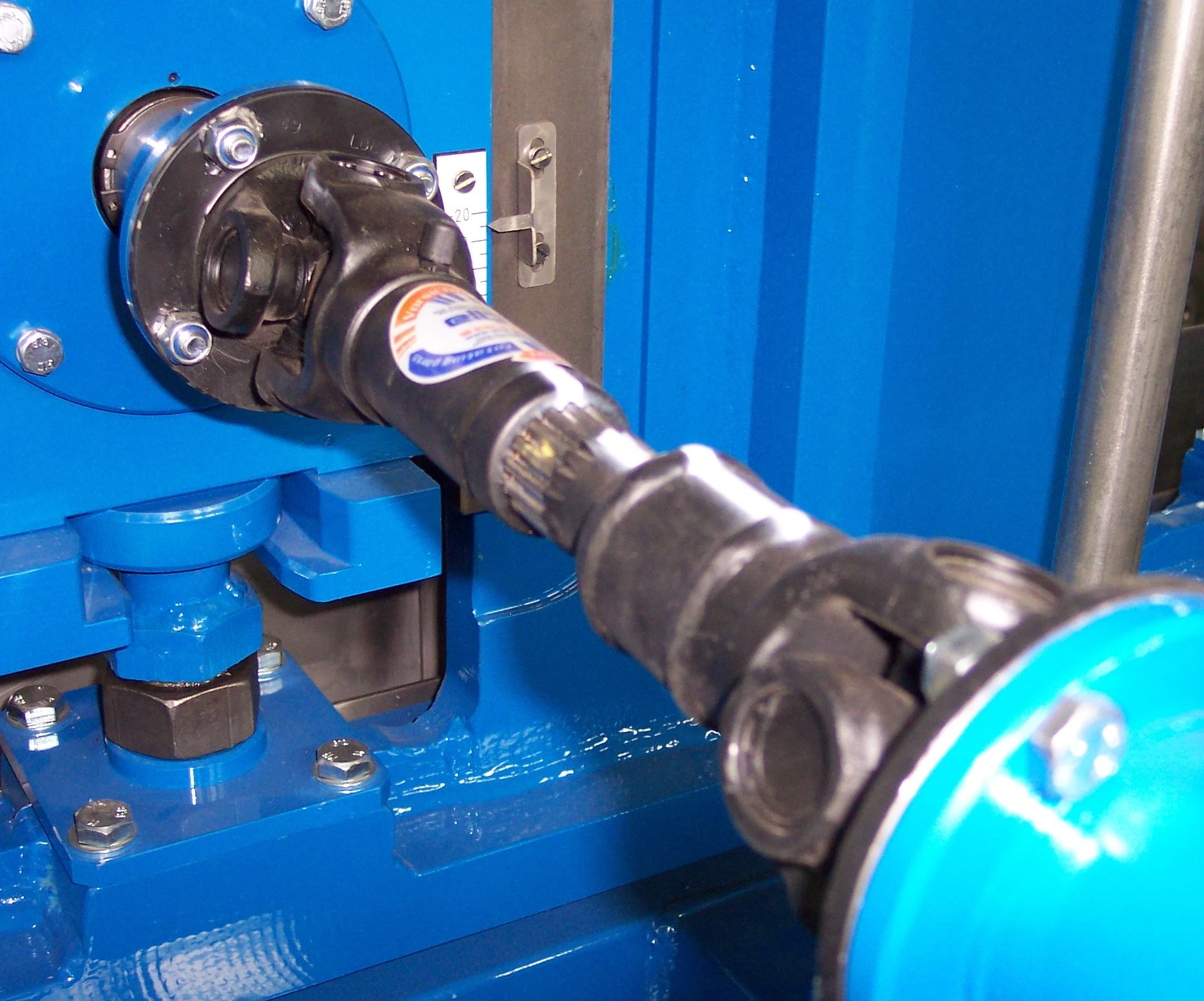

Universal joints in a driveshaft
A configuration known as a double Cardan joint drive shaft partially overcomes the problem of jerky rotation. This configuration uses two U-joints joined by an intermediate shaft, with the second U-joint phased in relation to the first U-joint to cancel the changing angular velocity. In this configuration, the angular velocity of the driven shaft will match that of the driving shaft, provided that both the driving shaft and the driven shaft are at equal angles with respect to the intermediate shaft (but not necessarily in the same plane) and that the two universal joints are 90 degrees out of phase. This assembly is commonly employed in rear wheel drive vehicles, where it is known as a drive shaft or propeller (prop) shaft.
Even when the driving and driven shafts are at equal angles with respect to the intermediate shaft, if these angles are greater than zero, oscillating moments are applied to the three shafts as they rotate. These tend to bend them in a direction perpendicular to the common plane of the shafts. This applies forces to the support bearings and can cause "launch shudder" in rear wheel drive vehicles.[13] The intermediate shaft will also have a sinusoidal component to its angular velocity, which contributes to vibration and stresses.
Mathematically, this can be shown as follows: If and are the angles for the input and output of the universal joint connecting the drive and the intermediate shafts respectively, and and are the angles for the input and output of the universal joint connecting the intermediate and the output shafts respectively, and each pair are at angle with respect to each other, then:


If the second universal joint is rotated 90 degrees with respect to the first, then . Using the fact that yields:


and it is seen that the output drive is just 90 degrees out of phase with the input shaft, yielding a constant-velocity drive.
Double Cardan Joint
- Main article: Constant-velocity joint#Double Cardan
A double cardan joint consists of two universal joints mounted back to back with a center yoke; the center yoke replaces the intermediate shaft. Provided that the angle between the input shaft and center yoke is equal to the angle between the center yoke and the output shaft, the second cardan joint will cancel the velocity errors introduced by the first cardan joint and the aligned double cardan joint will act as a CV joint.
Thompson Coupling
- Main article: Constant-velocity joint#Thompson coupling
A Thompson Coupling is a refined version of the double Cardan joint. It offers slightly increased efficiency with the penalty of great increase in complexity.
See also
- Twin Spring Coupling
- Cardan shaft
- Constant-velocity joint
- Elastic coupling
- Gear coupling
- Rag joint
- Canfield joint
References
- Theory of Machines 3 from National University of Ireland
- ↑ 1.0 1.1 Mills, Allan, "Robert Hooke's 'universal joint' and its application to sundials and the sundial-clock", Notes & Records of the Royal Society, 2007, accessed online 2010-06-16
- ↑ "universal, a. (adv.) and n.", para.13, Oxford English Dictionary Online, accessed 2010-06-16
- ↑ 3.0 3.1 Review of Ferdinand Berthoud's Treatise on Marine Clocks, Appendix Art. VIII, The Monthly Review or Literary Journal, Vol. L, 1774; see footnote, page 565.
- ↑ Edmund P. Morewood, Improvement in Coating Iron and Copper, U.S. Patent 3,746, Sept. 17, 1844.
- ↑ Dionysius Lardner, Handbook of Natural Philosophy, Lockwood, 1877; pages 292-293.
- ↑ Julius Weisbach and Gustav Herrmann, translated by J. L. Klein, Chapter I, Sections 26 and 27, Mechanics of Engineering and of Machinery, Vol. III, Wiley, 1883; pages 81-91.
- ↑ G. B. Airy, Account of the Northumberland Equatoreal and Dome Attached to the Cambridge Observatory, Cambridge University Press, 1844; pages 14, 17, 20, 23, 33 and plates VI, VII, IX, XI, XV, XVII.
- ↑ Ephraim Shay, Locomotive-Engine, U.S. Patent 242,992, June 14, 1881.
- ↑ Charles H. Amidon, Bit-Brace, U.S. Patent 298,542, May 13, 1884.
- ↑ The Tower Spherical Engine
- ↑ William P. Blake, Report of the Commissioner to the Paris Exposition, 1867, Chapter 1, Transactions of the California State Agricultural Society, During the Years 1866 and 1867, Vol X, Gelwicks, Sacramento, 1868.
- ↑ The Dynamometer Balance, [Van Nostrand's Engineering Magazine], Vol. XXV, No. CLVI (Dec. 1881); page 471.
- ↑ Electronically-controlled adjustable height bearing support bracket - US Patent 6345680
External links
- Universal Joint Shaft Applications
- [1] by Sándor Kabai, Wolfram Demonstrations Project.
- DIY: Replacing Universal Joints at About.com.
- Thompson Couplings Limited explanation of the Thompson coupling.
- The Thompson Coupling - invented by Glenn Thompson by ABC Television (The New Inventors, broadcast Feb 2007).
- U.S. Patent 7,144,326 (constant velocity coupling).
- About universal joints at McMaster Carr.
| |||||||||||||||||
| This page uses some content from Wikipedia. The original article was at Universal joint. The list of authors can be seen in the page history. As with Tractor & Construction Plant Wiki, the text of Wikipedia is available under the Creative Commons by Attribution License and/or GNU Free Documentation License. Please check page history for when the original article was copied to Wikia |