|
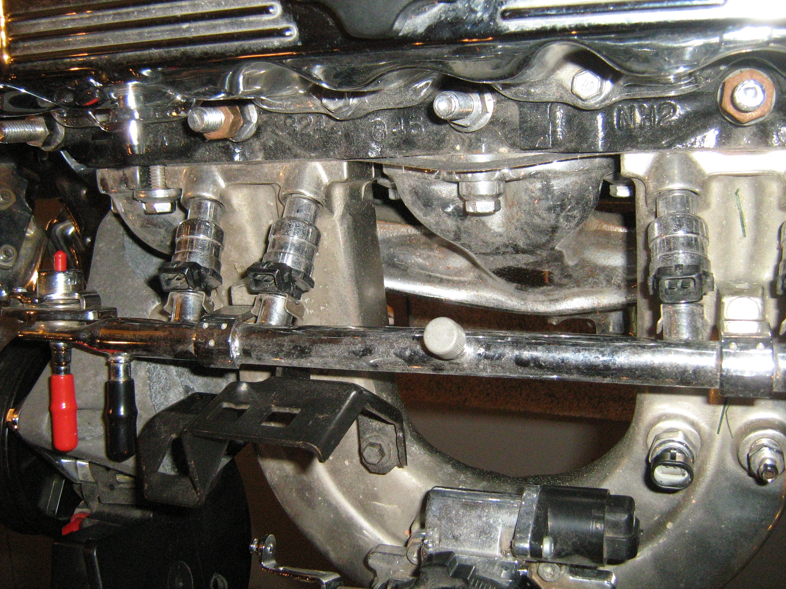
Fuel rail connected to the injectors that are mounted just above the intake manifold on a four cylinder engine.
Fuel injection is a system for admitting fuel into an internal combustion engine. It has become the primary fuel delivery system used in automotive petrol engines, having almost completely replaced carburetors during the late 1980s.
A fuel injection system is designed and calibrated specifically for the type(s) of fuel it will handle. Most fuel injection systems are for gasoline or diesel applications. With the advent of electronic fuel injection (EFI), the diesel and gasoline hardware has become similar. EFI's programmable firmware has permitted common hardware to be used with different fuels.
Carburetors were the predominant method used to meter fuel on gasoline engines before the widespread use of fuel injection. A variety of injection systems have existed since the earliest usage of the internal combustion engine.
The primary difference between carburetors and fuel injection is that fuel injection atomizes the fuel by forcibly pumping it through a small nozzle under high pressure, while a carburetor relies on suction created by intake air rushing through a venturi to draw the fuel into the airstream.
Objectives[]
The functional objectives for fuel injection systems can vary. All share the central task of supplying fuel to the combustion process, but it is a design decision how a particular system will be optimized. There are several competing objectives such as:
- power output
- fuel efficiency
- emissions performance
- ability to accommodate alternative fuels
- reliability
- driveability and smooth operation
- initial cost
- maintenance cost
- diagnostic capability
- range of environmental operation
- Engine tuning
Certain combinations of these goals are conflicting, and it is impractical for a single engine control system to fully optimize all criteria simultaneously. In practice, automotive engineers strive to best satisfy a customer's needs competitively. The modern digital electronic fuel injection system is far more capable at optimizing these competing objectives consistently than a carburetor. Carburetors have the potential to atomize fuel better (see Pogue and Allen Caggiano patents).
Benefits[]
Engine operation[]
Operational benefits to the driver of a fuel-injected car include smoother and more dependable engine response during quick throttle transitions, easier and more dependable engine starting, better operation at extremely high or low ambient temperatures, increased maintenance intervals, and increased fuel efficiency. On a more basic level, fuel injection does away with the choke which on carburetor-equipped vehicles must be operated when starting the engine from cold and then adjusted as the engine warms up.
An engine's air/fuel ratio must be precisely controlled under all operating conditions to achieve the desired engine performance, emissions, driveability, and fuel economy. Modern electronic fuel-injection systems meter fuel very accurately, and use closed loop fuel-injection quantity-control based on a variety of feedback signals from an oxygen sensor, a mass airflow (MAF) or manifold absolute pressure (MAP) sensor, a throttle position (TPS), and at least one sensor on the crankshaft and/or camshaft(s) to monitor the engine's rotational position. Fuel injection systems can react rapidly to changing inputs such as sudden throttle movements, and control the amount of fuel injected to match the engine's dynamic needs across a wide range of operating conditions such as engine load, ambient air temperature, engine temperature, fuel octane level, and atmospheric pressure.
A multipoint fuel injection system generally delivers a more accurate and equal mass of fuel to each cylinder than can a carburetor, thus improving the cylinder-to-cylinder distribution. Exhaust emissions are cleaner because the more precise and accurate fuel metering reduces the concentration of toxic combustion byproducts leaving the engine, and because exhaust cleanup devices such as the catalytic converter can be optimized to operate more efficiently since the exhaust is of consistent and predictable composition.
Fuel injection generally increases engine fuel efficiency. With the improved cylinder-to-cylinder fuel distribution, less fuel is needed for the same power output. When cylinder-to-cylinder distribution is less than ideal, as is always the case to some degree with a carburetor or throttle body fuel injection, some cylinders receive excess fuel as a side effect of ensuring that all cylinders receive sufficient fuel. Power output is asymmetrical with respect to air/fuel ratio; burning extra fuel in the rich cylinders does not reduce power nearly as quickly as burning too little fuel in the lean cylinders. However, rich-running cylinders are undesirable from the standpoint of exhaust emissions, fuel efficiency, engine wear, and engine oil contamination. Deviations from perfect air/fuel distribution, however subtle, affect the emissions, by not letting the combustion events be at the chemically ideal (stoichiometric) air/fuel ratio. Grosser distribution problems eventually begin to reduce efficiency, and the grossest distribution issues finally affect power. Increasingly poorer air/fuel distribution affects emissions, efficiency, and power, in that order. By optimizing the homogeneity of cylinder-to-cylinder mixture distribution, all the cylinders approach their maximum power potential and the engine's overall power output improves.
A fuel-injected engine often produces more power than an equivalent carbureted engine. Fuel injection alone does not necessarily increase an engine's maximum potential output. Increased airflow is needed to burn more fuel, which in turn releases more energy and produces more power. The combustion process converts the fuel's chemical energy into heat energy, whether the fuel is supplied by fuel injectors or a carburetor. However, airflow is often improved with fuel injection, the components of which allow more design freedom to improve the air's path into the engine. In contrast, a carburetor's mounting options are limited because it is larger, it must be carefully oriented with respect to gravity, and it must be equidistant from each of the engine's cylinders to the maximum practicable degree. These design constraints generally compromise airflow into the engine. Furthermore, a carburetor relies on a restrictive venturi to create a local air pressure difference, which forces the fuel into the air stream. The flow loss caused by the venturi, however, is small compared to other flow losses in the induction system. In a well-designed carburetor induction system, the venturi is not a significant airflow restriction.
Fuel is saved while the car is coasting because the car's movement is helping to keep the engine rotating, so less fuel is used for this purpose. Control units on modern cars react to this and reduce or stop fuel flow to the engine reducing wear on the brakes[citation needed].
History and development[]
Herbert Akroyd Stuart developed the first system laid out on modern lines (with a highly accurate 'jerk pump' to meter out fuel oil at high pressure to an injector. This system was used on the hot bulb engine and was adapted and improved by Robert Bosch and Clessie Cummins for use on diesel engines — Rudolf Diesel's original system employed a cumbersome 'air-blast' system using highly compressed air[clarification needed][citation needed].
The first use of direct gasoline injection was on the Hesselman engine invented by Swedish engineer Jonas Hesselman in 1925.[1][2] Hesselman engines use the ultra lean burn principle; fuel is injected toward the end of the compression stroke, then ignited with a spark plug. They are often started on gasoline and then switched to diesel or kerosene.[3] Fuel injection was in widespread commercial use in diesel engines by the mid-1920s. Because of its greater immunity to wildly changing g-forces on the engine, the concept was adapted for use in gasoline-powered aircraft during World War II, and direct injection was employed in some notable designs like the Junkers Jumo 210, the Daimler-Benz DB 601, the BMW 801, the Shvetsov ASh-82FN (M-82FN) and later versions of the Wright R-3350 used in the B-29 Superfortress.
Alfa Romeo tested one of the very first electric injection systems (Caproni-Fuscaldo) in Alfa Romeo 6C2500 with "Ala spessa" body in 1940 Mille Miglia. The engine had six electrically operated injectors and were fed by a semi-high pressure circulating fuel pump system.[citation needed]
Mechanical[]
The term Mechanical when applied to fuel injection is used to indicate that metering functions of the fuel injection (how the correct amount of fuel for any given situation is determined and delivered) is not achieved electronically but rather through mechanical means alone.
In the 1940s, hot rodder Stuart Hilborn offered mechanical injection for racers, salt cars, and midgets.[4]
One of the first commercial gasoline injection systems was a mechanical system developed by Bosch and introduced in 1952 on the Goliath GP700 and Gutbrod Superior 600. This was basically a high pressure diesel direct-injection pump with an intake throttle valve set up. (Diesels only change amount of fuel injected to vary output; there is no throttle.) This system used a normal gasoline fuel pump, to provide fuel to a mechanically driven injection pump, which had separate plungers per injector to deliver a very high injection pressure directly into the combustion chamber.
Another mechanical system, also by Bosch, but injecting the fuel into the port above the intake valve was later used by Porsche from 1969 until 1973 for the 911 production range and until 1975 on the Carrera 3.0 in Europe. Porsche continued using it on its racing cars into the late seventies and early eighties. Porsche racing variants such as the 911 RSR 2.7 & 3.0, 904/6, 906, 907, 908, 910, 917 (in its regular normally aspirated or 5.5 Liter/1500 HP Turbocharged form), and 935 all used Bosch or Kugelfischer built variants of injection. The Kugelfischer system was also used by the BMW 2000/2002 Tii and some versions of the Peugeot 404/504 and Lancia Flavia. Lucas also offered a mechanical system which was used by some Maserati, Aston Martin and Triumph models between ca. 1963 and 1973.
A system similar to the Bosch inline mechanical pump was built by SPICA for Alfa Romeo, used on the Alfa Romeo Montreal and on US market 1750 and 2000 models from 1969 to 1981. This was specifically designed to meet the US emission requirements, and allowed Alfa to meet these requirements with no loss in performance and a reduction in fuel consumption.
Chevrolet introduced a mechanical fuel injection option, made by General Motors' Rochester Products division, for its 283 V8 engine in 1956 (1957 US model year). This system directed the inducted engine air across a "spoon shaped" plunger that moved in proportion to the air volume. The plunger connected to the fuel metering system which mechanically dispensed fuel to the cylinders via distribution tubes. This system was not a "pulse" or intermittent injection, but rather a constant flow system, metering fuel to all cylinders simultaneously from a central "spider" of injection lines. The fuel meter adjusted the amount of flow according to engine speed and load, and included a fuel reservoir, which was similar to a carburetor's float chamber. With its own high-pressure fuel pump driven by a cable from the distributor to the fuel meter, the system supplied the necessary pressure for injection. This was "port" injection, however, in which the injectors are located in the intake manifold, very near the intake valve. (Direct fuel injection is a fairly recent innovation for automobile engines. As recent as 1954 in the aforementioned Mercedes-Benz 300SL or the Gutbrod in 1953.) The highest performance version of the fuel injected engine was rated at 283 bhp (211.0 kW) from 283 cubic inches (4.6 L). This made it among the early production engines in history to exceed 1 hp/in³ (45.5 kW/L), after Chrysler's Hemi engine and a number of others. General Motors' fuel injected engine — usually referred to as the "fuelie" — was optional on the Corvette for the 1957 model year.
During the 1960s, other mechanical injection systems such as Hilborn were occasionally used on modified American V8 engines in various racing applications such as drag racing, oval racing, and road racing.[5] These racing-derived systems were not suitable for everyday street use, having no provisions for low speed metering or often none even for starting (fuel had to be squirted into the injector tubes while cranking the engine in order to start it). However they were a favorite in the aforementioned competition trials in which essentially wide-open throttle operation was prevalent. Constant-flow injection systems continue to be used at the highest levels of drag racing, where full-throttle, high-RPM performance is key.[6]
Electronic[]
The first commercial electronic fuel injection (EFI) system was Electrojector, developed by the Bendix Corporation and was to be offered by American Motors (AMC) in 1957.[7][8] A special muscle car model, the Rambler Rebel, showcased AMC's new 327 cu in (5.4 L) engine. The Electrojector was an option and rated at 288 bhp (214.8 kW).[9] With no Venturi effect or heated carburetor (to help vaporize the gasoline) AMC's EFI equipped engine breathed easier with denser cold air to pack more power sooner, reaching peak torque at 500 rpm lower than the equivalent no-fuel injection engine.[5] The Rebel Owners Manual described the design and operation of the new system.[10] Initial press information about the Bendix system in December 1956 was followed in March 1957 by a price bulletin that pegged the option at US$395, but due to supplier difficulties, fuel-injected Rebels would only be available after June 15.[11] This was to have been the first production EFI engine, but Electrojector's teething problems meant only pre-production cars were so equipped: thus, very few cars so equipped were ever sold[12] and none were made available to the public.[13] The EFI system in the Rambler was a far more-advanced setup than the mechanical types then appearing on the market and the engines ran fine in warm weather, but suffered hard starting in cooler temperatures.[11]
Chrysler offered Electrojector on the 1958 Chrysler 300D, Dodge D500, Plymouth Fury, and DeSoto Adventurer, arguably the first series-production cars equipped with an EFI system. It was jointly engineered by Chrysler and Bendix. The early electronic components were not equal to the rigors of underhood service, however, and were too slow to keep up with the demands of "on the fly" engine control. Most of the 35 vehicles originally so equipped were field-retrofitted with 4-barrel carburetors. The Electrojector patents were subsequently sold to Bosch.
Bosch developed an electronic fuel injection system, called D-Jetronic (D for Druck, German for "pressure"), which was first used on the VW 1600TL/E in 1967. This was a speed/density system, using engine speed and intake manifold air density to calculate "air mass" flow rate and thus fuel requirements. This system was adopted by VW, Mercedes-Benz, Porsche, Citroën, Saab, and Volvo. Lucas licensed the system for production with Jaguar. Bosch superseded the D-Jetronic system with the K-Jetronic and L-Jetronic systems for 1974, though some cars (such as the Volvo 164) continued using D-Jetronic for the following several years.

Chevrolet Cosworth Vega engine showing Bendix electronic fuel injection
The Cadillac Seville was introduced in 1975 with an EFI system made by Bendix and modelled very closely on Bosch's D-Jetronic. L-Jetronic first appeared on the 1974 Porsche 914, and uses a mechanical airflow meter (L for Luft, German for "air") that produces a signal that is proportional to "air volume". This approach required additional sensors to measure the atmospheric pressure and temperature, to ultimately calculate "air mass". L-Jetronic was widely adopted on European cars of that period, and a few Japanese models a short time later.
The limited production Chevrolet Cosworth Vega was introduced in March 1975 using a Bendix EFI system with pulse-time manifold injection, four injector valves, an electronic control unit (ECU), five independent sensors and two fuel pumps. The EFI system was developed to satisfy stringent emission control requirements and market demands for a technologically advanced responsive vehicle. 5000 hand-built Cosworth Vega engines were produced but only 3508 cars were sold through 1976.[14]
A major milestone was reached in 1980 when Motorola Corporation introduced the first engine computer with microprocessor (digital) control, the EEC III module, which is now the standard approach. The advent of the digital microprocessor permitted the integration of all powertrain sub-systems into a single control module. [15]
In 1981 Chrysler Corporation introduced an EFI system featuring a sensor that directly measures the air mass flow into the engine, on the Imperial automobile (5.2L V8) as standard equipment. The mass air sensor utilizes a heated platinum wire placed in the incoming air flow. The rate of the wire's cooling is proportional to the air mass flowing across the wire. Since the hot wire sensor directly measures air mass, the need for additional temperature and pressure sensors was eliminated. This system was independently developed and engineered in Highland Park, Michigan and manufactured at Chrysler's Electronics division in Huntsville, Alabama, USA.[16][17]
Supersession of carburetors[]
| This article includes a list of references, related reading or external links, but its sources remain unclear because it lacks inline citations. Please improve this article by introducing more precise citations where appropriate. (May 2010) |
When efficient combustion takes place in an internal combustion engine, the proper number of fuel molecules and oxygen molecules are sent to the engine's combustion chamber(s), where fuel combustion (i.e., fuel oxidation) takes place. When efficient combustion takes place, neither extra fuel or extra oxygen molecules remain: each fuel molecule is matched with the appropriate number of oxygen molecules. This balanced condition is called stoichiometry.
In the 1970s and 1980s in the US, the federal government imposed increasingly strict exhaust emission regulations. During that time period, the vast majority of gasoline-fueled automobile and light truck engines did not use fuel injection. To comply with the new regulations, automobile manufacturers often made extensive and complex modifications to the engine carburetor(s). While a simple carburetor system has certain advantages compared to the fuel injection systems that were available during the 1970s and 1980s (including lower manufacturing cost), the more complex carburetor systems installed on many engines beginning in the early 1970s did not usually have these advantages. So in order to more easily comply with government emissions control regulations, automobile manufacturers, beginning in the late 1970s, furnished more of their gasoline-fueled engines with fuel injection systems, and fewer with complex carburetor systems.
There are three primary types of toxic emissions from an internal combustion engine: Carbon Monoxide (CO), unburnt hydrocarbons (HC), and oxides of nitrogen (NOx). CO and HC result from incomplete combustion of fuel due to insufficient oxygen in the combustion chamber. NOx, in contrast, results from excessive oxygen in the combustion chamber. The opposite causes of these pollutants makes it difficult to control all three simultaneously. Once the permissible emission levels dropped below a certain point, catalytic treatment of these three main pollutants became necessary. This required a particularly large increase in fuel metering accuracy and precision, for simultaneous catalysis of all three pollutants requires that the fuel/air mixture be held within a very narrow range of stoichiometry. The open loop fuel injection systems had already improved cylinder-to-cylinder fuel distribution and engine operation over a wide temperature range, but did not offer sufficient fuel/air mixture control to enable effective exhaust catalysis. Closed loop fuel injection systems improved the air/fuel mixture control with an exhaust gas oxygen sensor. The O2 sensor is mounted in the exhaust system upstream of the catalytic converter, and enables the engine management computer to determine and adjust the air/fuel ratio precisely and quickly.
Fuel injection was phased in through the latter '70s and '80s at an accelerating rate, with the US, French and German markets leading and the UK and Commonwealth markets lagging somewhat, and since the early 1990s, almost all gasoline passenger cars sold in first world markets like the United States, Canada, Europe, Japan, and Australia have come equipped with electronic fuel injection (EFI). Many motorcycles still utilize carbureted engines, though all current high-performance designs have switched to EFI.
Fuel injection systems have evolved significantly since the mid-1980s. Current systems provide an accurate, reliable and cost-effective method of metering fuel and providing maximum engine efficiency with clean exhaust emissions, which is why EFI systems have replaced carburetors in the marketplace. EFI is becoming more reliable and less expensive through widespread usage. At the same time, carburetors are becoming less available, and more expensive. Even marine applications are adopting EFI as reliability improves. Virtually all internal combustion engines, including motorcycles, off-road vehicles, and outdoor power equipment, may eventually use some form of fuel injection.
The carburetor remains in use in developing countries where vehicle emissions are unregulated and diagnostic and repair infrastructure is sparse. Fuel injection is gradually replacing carburetors in these nations too as they adopt emission regulations conceptually similar to those in force in Europe, Japan, Australia and North America. NASCAR will legalize and adopt fuel injectors to take the place of carburetors starting at the 2012 NASCAR Sprint Cup Series season.[18][19][20]
Basic function[]
| This article includes a list of references, related reading or external links, but its sources remain unclear because it lacks inline citations. Please improve this article by introducing more precise citations where appropriate. (May 2010) |
The process of determining the necessary amount of fuel, and its delivery into the engine, are known as fuel metering. Early injection systems used mechanical methods to meter fuel (non electronic, or mechanical fuel injection). Modern systems are nearly all electronic, and use an electronic solenoid (the injector) to inject the fuel. An electronic engine control unit calculates the mass of fuel to inject.
Modern fuel injection schemes follow much the same setup. There is a mass airflow sensor or manifold absolute pressure sensor at the intake, typically mounted either in the air tube feeding from the air filter box to the throttle body, or mounted directly to the throttle body itself. The mass airflow sensor does exactly what its name implies; it senses the mass of the air that flows past it, giving the computer an accurate idea of how much air is entering the engine. The next component in line is the Throttle Body. The throttle body has a throttle position sensor mounted onto it, typically on the butterfly valve of the throttle body. The throttle position sensor (TPS) reports to the computer the position of the throttle butterfly valve, which the ECM uses to calculate the load upon the engine. The fuel system consists of a fuel pump (typically mounted in-tank), a fuel pressure regulator, fuel lines (composed of either high strength plastic, metal, or reinforced rubber), a fuel rail that the injectors connect to, and the fuel injector(s). There is a coolant temperature sensor that reports the engine temperature to the ECM, which the engine uses to calculate the proper fuel ratio required. In sequential fuel injection systems there is a camshaft position sensor, which the ECM uses to determine which fuel injector to fire. The last component is the oxygen sensor. After the vehicle has warmed up, it uses the signal from the oxygen sensor to perform fine tuning of the fuel trim.
The fuel injector acts as the fuel-dispensing nozzle. It injects liquid fuel directly into the engine's air stream. In almost all cases this requires an external pump. The pump and injector are only two of several components in a complete fuel injection system.
In contrast to an EFI system, a carburetor directs the induction air through a venturi, which generates a minute difference in air pressure. The minute air pressure differences both emulsify (premix fuel with air) the fuel, and then acts as the force to push the mixture from the carburetor nozzle into the induction air stream. As more air enters the engine, a greater pressure difference is generated, and more fuel is metered into the engine. A carburetor is a self-contained fuel metering system, and is cost competitive when compared to a complete EFI system.
An EFI system requires several peripheral components in addition to the injector(s), in order to duplicate all the functions of a carburetor. A point worth noting during times of fuel metering repair is that early EFI systems are prone to diagnostic ambiguity. A single carburetor replacement can accomplish what might require numerous repair attempts to identify which one of the several EFI system components is malfunctioning. Newer EFI systems since the advent of OBD II diagnostic systems, can be very easy to diagnose due to the increased ability to monitor the realtime data streams from the individual sensors. This gives the diagnosing technician realtime feedback as to the cause of the drivability concern, and can dramatically shorten the number of diagnostic steps required to ascertain the cause of failure, something which isn't as simple to do with a carburetor. On the other hand, EFI systems require little regular maintenance; a carburetor typically requires seasonal and/or altitude adjustments.
Detailed function[]
| This article includes a list of references, related reading or external links, but its sources remain unclear because it lacks inline citations. Please improve this article by introducing more precise citations where appropriate. (May 2010) |
Note: These examples specifically apply to a modern EFI gasoline engine. Parallels to fuels other than gasoline can be made, but only conceptually.
Typical EFI components[]
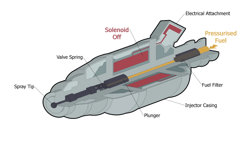
Animated cut through diagram of a typical fuel injector.
- Injectors
- Fuel Pump
- Fuel Pressure Regulator
- ECM - Engine Control Module; includes a digital computer and circuitry to communicate with sensors and control outputs.
- Wiring Harness
- Various Sensors (Some of the sensors required are listed here.)
- Crank/Cam Position: Hall effect sensor
- Airflow: MAF sensor, sometimes this is inferred with a MAP sensor
- Exhaust Gas Oxygen: Oxygen sensor, EGO sensor, UEGO sensor
Functional description[]
Central to an EFI system is a computer called the Engine Control Unit (ECU), which monitors engine operating parameters via various sensors. The ECU interprets these parameters in order to calculate the appropriate amount of fuel to be injected, among other tasks, and controls engine operation by manipulating fuel and/or air flow as well as other variables. The optimum amount of injected fuel depends on conditions such as engine and ambient temperatures, engine speed and workload, and exhaust gas composition.
The electronic fuel injector is normally closed, and opens to inject pressurized fuel as long as electricity is applied to the injector's solenoid coil. The duration of this operation, called the pulse width, is proportional to the amount of fuel desired. The electric pulse may be applied in closely controlled sequence with the valve events on each individual cylinder (in a sequential fuel injection system), or in groups of less than the total number of injectors (in a batch fire system).
Since the nature of fuel injection dispenses fuel in discrete amounts, and since the nature of the 4-stroke engine has discrete induction (air-intake) events, the ECU calculates fuel in discrete amounts. In a sequential system, the injected fuel mass is tailored for each individual induction event. Every induction event, of every cylinder, of the entire engine, is a separate fuel mass calculation, and each injector receives a unique pulse width based on that cylinder's fuel requirements.
It is necessary to know the mass of air the engine "breathes" during each induction event. This is proportional to the intake manifold's air pressure/temperature, which is proportional to throttle position. The amount of air inducted in each intake event is known as "air-charge", and this can be determined using several methods. (See MAF sensor, and MAP sensor.)
The three elemental ingredients for combustion are fuel, air and ignition. However, complete combustion can only occur if the air and fuel is present in the exact stoichiometric ratio, which allows all the carbon and hydrogen from the fuel to combine with all the oxygen in the air, with no undesirable polluting leftovers. Oxygen sensors monitor the amount of oxygen in the exhaust, and the ECU uses this information to adjust the air-to-fuel ratio in real-time.
To achieve stoichiometry, the air mass flow into the engine is measured and multiplied by the stoichiometric air/fuel ratio 14.64:1 (by weight) for gasoline. The required fuel mass that must be injected into the engine is then translated to the required pulse width for the fuel injector. The stoichiometric ratio changes as a function of the fuel; diesel, gasoline, ethanol, methanol, propane, methane (natural gas), or hydrogen.
Deviations from stoichiometry are required during non-standard operating conditions such as heavy load, or cold operation, in which case, the mixture ratio can range from 10:1 to 18:1 (for gasoline). In early fuel injection systems this was accomplished with a thermotime switch.
Pulse width is inversely related to pressure difference across the injector inlet and outlet. For example, if the fuel line pressure increases (injector inlet), or the manifold pressure decreases (injector outlet), a smaller pulse width will admit the same fuel. Fuel injectors are available in various sizes and spray characteristics as well. Compensation for these and many other factors are programmed into the ECU's software.
Sample pulsewidth calculations[]
Note: These calculations are based on a 4-stroke-cycle, 5.0L, V-8, gasoline engine. The variables used are real data.
Calculate injector pulsewidth from airflow[]
- First the CPU determines the air mass flow rate from the sensors - . (The various methods to determine airflow are beyond the scope of this topic. See MAF sensor, or MAP sensor.)


- is the reciprocal of engine speed (RPM).

- The term , whether it's a four stroke or a two-stroke engine.


- is the desired mixture ratio, usually stoichiometric, but often different depending on operating conditions.


- is the flow capacity of the injector, or its size.

- Combining the above three terms . . .

- Substituting real variables for the 5.0 L engine at idle.
- *

- Substituting real variables for the 5.0 L engine at maximum power.
- *

.jpg)
Injector pulsewidth typically ranges from 4 ms/engine-cycle at idle, to 35 ms per engine-cycle at wide-open throttle. The pulsewidth accuracy is approximately 0.01 ms.
Calculate fuel-flow rate from pulsewidth[]
- (Fuel flow rate) ≈ (pulsewidth) × (engine speed) × (number of fuel injectors)
- Looking at it another way:
- (Fuel flow rate) ≈ (throttle position) × (rpm) × (cylinders)
- Looking at it another way:
- (Fuel flow rate) ≈ (air-charge) × (fuel/air) × (rpm) × (cylinders)
- Substituting real variables for the 5.0 L engine at idle.
- (Fuel flow rate) = (2.0 ms/intake-stroke) × (hour/3,600,000 ms) × (24 lb-fuel/hour) × (4-intake-stroke/rev) × (700 rev/min) × (60 min/h) = (2.24 lb/h)
- Substituting real variables for the 5.0L engine at maximum power.
- (Fuel flow rate) = (17.3 ms/intake-stroke) × (hour/3,600,000-ms) × (24 lb-fuel/hour) × (4-intake-stroke/rev) × (5500-rev/min) × (60-min/hour) = (152 lb/h)
The fuel consumption rate is 68 times greater at maximum engine output than at idle. This dynamic range of fuel flow is typical of a naturally aspirated passenger car engine. The dynamic range is greater on a supercharged or turbocharged engine. It is interesting to note that 15 gallons of gasoline will be consumed in 37 minutes if maximum output is sustained. On the other hand, this engine could continuously idle for almost 42 hours on the same 15 gallons.
Various injection schemes[]
| This article includes a list of references, related reading or external links, but its sources remain unclear because it lacks inline citations. Please improve this article by introducing more precise citations where appropriate. (May 2010) |
Single-point injection[]
Single-point injection, called Throttle-body injection (TBI) by General Motors and Central Fuel Injection (CFI) by Ford, was introduced in the 1940s in large aircraft engines (then called the pressure carburetor) and in the 1980s in the automotive world. The SPI system injects fuel at the throttle body (the same location where a carburetor introduced fuel). The induction mixture passes through the intake runners like a carburetor system, and is thus labelled a "wet manifold system". Fuel pressure is usually specified to be in the area of 10-15 psi. The justification for single-point injection was low cost. Many of the carburetor's supporting components could be reused such as the air cleaner, intake manifold, and fuel line routing. This postponed the redesign and tooling costs of these components. Most of these components were later redesigned for the next phase of fuel injection's evolution, which is individual port injection, commonly known as MPFI or "multi-point fuel injection". TBI was used extensively on American-made passenger cars and light trucks in the 1980-1995 timeframe and some transition-engined European cars throughout the early and mid-1990s. Mazda called their system EGI, and even introduced an electronically controlled version called the EGI-S.
Continuous injection[]
In a continuous injection system, fuel flows at all times from the fuel injectors, but at a variable flow rate. This is in contrast to most fuel injection systems, which provide fuel during short pulses of varying duration, with a constant rate of flow during each pulse. Continuous injection systems can be multi-point or single-point, but not direct.
The most common automotive continuous injection system is Bosch's K-Jetronic (K for kontinuierlich, German for "continuous" — a.k.a. CIS — Continuous Injection System), introduced in 1974. Gasoline is pumped from the fuel tank to a large control valve called a fuel distributor, which separates the single fuel supply pipe from the tank into smaller pipes, one for each injector. The fuel distributor is mounted atop a control vane through which all intake air must pass, and the system works by varying fuel volume supplied to the injectors based on the angle of the air vane, which in turn is determined by the volume flowrate of air past the vane, and by the control pressure. The control pressure is regulated with a mechanical device called the control pressure regulator (CPR) or the warm-up regulator (WUR). Depending on the model, the CPR may be used to compensate for altitude, full load, and/or a cold engine. On cars equipped with an oxygen sensor, the fuel mixture is adjusted by a device called the frequency valve. The injectors are simple spring-loaded check valves with nozzles; once fuel system pressure becomes high enough to overcome the counterspring, the injectors begin spraying. K-Jetronic was used for many years between 1974 and the mid 1990s by BMW, Lamborghini, Ferrari, Mercedes-Benz, Volkswagen, Ford, Porsche, Audi, Saab, DeLorean, and Volvo. There was also a variant of the system called KE-Jetronic with electronic instead of mechanical control of the control pressure. Some Toyotas and other Japanese cars from the 1970s to the early 1990s used an application of Bosch's multipoint L-Jetronic system manufactured under license by DENSO. Chrysler used a similar continuous fuel injection system on the 1981-1983 Imperial.
In piston aircraft engines, continuous-flow fuel injection is the most common type. In contrast to automotive fuel injection systems, aircraft continuous flow fuel injection is all mechanical, requiring no electricity to operate. Two common types exist: the Bendix RSA system, and the TCM system. The Bendix system is a direct descendant of the pressure carburetor. However, instead of having a discharge valve in the barrel, it uses a flow divider mounted on top of the engine, which controls the discharge rate and evenly distributes the fuel to stainless steel injection lines which go to the intake ports of each cylinder. The TCM system is even more simple. It has no venturi, no pressure chambers, no diaphragms, and no discharge valve. The control unit is fed by a constant-pressure fuel pump. The control unit simply uses a butterfly valve for the air which is linked by a mechanical linkage to a rotary valve for the fuel. Inside the control unit is another restriction which is used to control the fuel mixture. The pressure drop across the restrictions in the control unit controls the amount of fuel flowing, so that fuel flow is directly proportional to the pressure at the flow divider. In fact, most aircraft using the TCM fuel injection system feature a fuel flow gauge which is actually a pressure gauge that has been calibrated in gallons per hour or pounds per hour of fuel.
Central port injection (CPI)[]
General Motors implemented a system called "central port injection" (CPI) or "central port fuel injection" (CPFI). It uses tubes with poppet valves from a central injector to spray fuel at each intake port rather than the central throttle-body[citation needed]. Pressure specifications typically mirror that of a TBI system. The two variants were CPFI from 1992 to 1995, and CSFI from 1996 and on[citation needed]. CPFI is a batch-fire system, in which fuel is injected to all ports simultaneously. The 1996 and later CSFI system sprays fuel sequentially.[21]
Multi-point fuel injection[]
Multi-point fuel injection injects fuel into the intake ports just upstream of each cylinder's intake valve, rather than at a central point within an intake manifold. MPFI (or just MPI) systems can be sequential, in which injection is timed to coincide with each cylinder's intake stroke; batched, in which fuel is injected to the cylinders in groups, without precise synchronization to any particular cylinder's intake stroke; or simultaneous, in which fuel is injected at the same time to all the cylinders. The intake is only slightly wet, and typical fuel pressure runs between 40-60 psi.
Many modern EFI systems utilize sequential MPFI; however, in newer gasoline engines, direct injection systems are beginning to replace sequential ones.
Direct injection[]
- See also: Common Rail
| This section needs additional citations for verification. Please help improve this article by adding citations to reliable sources. Unsourced material may be challenged and removed. (May 2010) |
Direct fuel injection costs more than indirect injection systems: the injectors are exposed to more heat and pressure, so more costly materials and higher-precision electronic management systems are required. However, the entire intake is dry, making this a very clean system. In a common rail system, the fuel from the fuel tank is supplied to the common header (called the accumulator). This fuel is then sent through tubing to the injectors which inject it into the combustion chamber. The header has a high pressure relief valve to maintain the pressure in the header and return the excess fuel to the fuel tank. The fuel is sprayed with the help of a nozzle which is opened and closed with a needle valve, operated with a solenoid. When the solenoid is not activated, the spring forces the needle valve into the nozzle passage and prevents the injection of fuel into the cylinder. The solenoid lifts the needle valve from the valve seat, and fuel under pressure is sent in the engine cylinder. Third-generation common rail diesels use piezoelectric injectors for increased precision, with fuel pressures up to 1,800 bar/26,000 psi.
Gasoline engines incorporate gasoline direct injection engine technology.
Diesel engines[]
Diesel engines must use fuel injection, and it must be timed (unlike on petrol engines). Throughout the early history of diesels, they were always fed by a mechanical pump with a small separate cylinder for each cylinder, feeding separate fuel lines and individual injectors. Most such pumps were in-line, though some were rotary.
Earlier systems, relying on crude injectors, often injected into a sub-chamber shaped to swirl the compressed air and improve combustion; this was known as indirect injection. However, it was less thermally efficient than the now universal direct injection in which initiation of combustion takes place in a depression (often toroidal) in the crown of the piston.
Petrol/gasoline engines[]
- Main article: gasoline direct injection
Modern petrol engines (gasoline engines) also utilise direct injection, which is referred to as gasoline direct injection. This is the next step in evolution from multi-point fuel injection, and offers another magnitude of emission control by eliminating the "wet" portion of the induction system along the inlet tract.
By virtue of better dispersion and homogeneity of the directly injected fuel, the cylinder and piston are cooled, thereby permitting higher compression ratios and more aggressive ignition timing, with resultant enhanced power output. More precise management of the fuel injection event also enables better control of emissions. Finally, the homogeneity of the fuel mixture allows for leaner air/fuel ratios, which together with more precise ignition timing can improve fuel efficiency. Along with this, the engine can operate with stratified (lean burn) mixtures, and hence avoid throttling losses at low and part engine load. Some direct-injection systems incorporate piezoelectronic fuel injectors. With their extremely fast response time, multiple injection events can occur during each cycle of each cylinder of the engine.
The first use of direct petrol injection was on the Hesselman engine, invented by Swedish engineer Jonas Hesselman in 1925.[22][23]
Maintenance hazards[]
Fuel injection introduces potential hazards in engine maintenance due to the high fuel pressures used. Residual pressure can remain in the fuel lines long after an injection-equipped engine has been shut down. This residual pressure must be relieved, and if it is done so by external bleed-off, the fuel must be safely contained. If a high-pressure diesel fuel injector is removed from its seat and operated in open air, there is a risk to the operator of injury by hypodermic jet-injection, even with only 100 psi (6.9 bar) pressure.[24] The first known such injury occurred in 1937 during a diesel engine maintenance operation.[25]
See also[]
- Carburetter
- Injector
- Injector pump
- Semi-diesel
- Glossary Index
Notes[]
- ↑ Scania fordonshistoria 1891-1991 av Björn-Eric Lindh, 1992. ISBN 91-7886-074-1
- ↑ Volvo – Lastbilarna igår och idag av Christer Olsson, 1987. ISBN 91-86442-76-7
- ↑ <www.directinjectionengine.com/
- ↑ Circle Track, 9/84, pp.82-3.
- ↑ 5.0 5.1 Walton, Harry (March 1957), "How Good is Fuel Injection?", Popular Science (Bonnier Corporation) 170(3): 88–93, http://books.google.com/?id=byEDAAAAMBAJ&pg=PA88&dq=1957+Rambler+fuel+injection&cd=18#v=onepage&q=. Retrieved on .
- ↑ http://www.hotrod.com/techarticles/engine/hrdp_1010_what_you_need_to_know_about_mechanical_fuel_injection/index.html
- ↑ Ingraham, Joseph C. "Automobiles: Races; Everybody Manages to Win Something At the Daytona Beach Contests" The New York Times, March 24, 1957. Page 153. Retrieved on December 15, 2007.
- ↑ Consumer Reports 22: 154. 1957.
- ↑ Holder, William (2006). Extreme Muscle Cars: The Factory Lightweight Legacy. Krause Publications, 16. ISBN 9780896892781. Retrieved on 2009-12-26.
- ↑ Excerpts from 1957 Rambler Rebel owner's manual, retrieved on 2009-12-26.
- ↑ 11.0 11.1 "Rambler Measures Up" by the Auto Editors of Consumer Guide, 2007-08-22, retrieved on 2009-12-26.
- ↑ Aird, Forbes (2001). Bosch fuel injection systems. HP Trade, 29. ISBN 9781557883650.
- ↑ American Musclecars: Power to the People, retrieved on 2009-12-26.
- ↑ 1975 Chevrolet Cosworth Vega Overhaul Supplement - general information
- ↑ http://www.motorola.com/staticfiles/Consumers/Corporate/US-EN/_Documents/Motorola_History_Timeline.pdf
- ↑ http://www.hemmings.com/hcc/stories/2008/07/01/hmn_feature22.html
- ↑ http://www.imperialclub.com/Yr/1981/81EFI/Cover.htm
- ↑ NASCAR sets fuel injection for '12 but keeping restrictor plates at USA Today
- ↑ NASCAR Moves to Fuel Injection, Bosch First Approved Supplier at Auto Service World
- ↑ Bosch to provide oxygen sensors for fuel injection at NASCAR.com
- ↑ 1997 Chevrolet Truck Service Manual, page 6A-24, drawing, item (3) Central Sequential Muliport injector.
- ↑ Scania fordonshistoria 1891-1991 av Björn-Eric Lindh, 1992. ISBN 91-7886-074-1 (Translated title: Vehicle history of Scania 1891-1991)
- ↑ Volvo – Lastbilarna igår och idag av Christer Olsson, 1987. ISBN 91-86442-76-7 (Translated title: Volvo trucks yesterday and today)
- ↑ Agha, F.P. (1978), "High-pressure paint gun injuries of hand: clinical and roentgen aspects", NY State Journal of Medicine 78: 1955–6.
- ↑ Rees, C.E. (1937), "Penetration of Tissue by Fuel Oil Under High Pressure from a Diesel Engine", Journal of the American Medical Association 109: 866–7.
External links[]
- History of the D Jetronic system
- High Quality Fuel System Repairs Guide
- How Fuel Injection Systems Work
| ||||||||||||||||||||
| This page uses some content from Wikipedia. The original article was at Fuel injection. The list of authors can be seen in the page history. As with Tractor & Construction Plant Wiki, the text of Wikipedia is available under the Creative Commons by Attribution License and/or GNU Free Documentation License. Please check page history for when the original article was copied to Wikia |