 | |
| Manufacturer | Bedford Vehicles |
|---|---|
| Parent company | Vauxhall Motors |
| Production | 1952–1969 |
| Assembly | Luton, United Kingdom |
| Successor | Bedford CF |
| Class | Light commercial vehicle |
| Body style(s) | Van |
| Layout | Longitudinal front engine, rear-wheel drive |
| Engine(s) |
1.5 L I4 OHV, 1.6 L I4 OHV |
| Transmission(s) |
3-speed manual, 4-speed manual |
| Wheelbase |
SWB: 90 in (2,286 mm) LWB: 102 in (2,591 mm) |
| Length |
SWB: 154 in (3,912 mm) LWB: 166 in (4,216 mm) |
| Width | 70.0 in (1,778 mm) |
| Height | 74.75 in (1,899 mm) |
| Kerb weight |
SWB: 2,245 lb (1,018 kg) LWB: 2,345 lb (1,064 kg) |
| Related | Bedford Dormobile |

_reg_MSL_292_at_Boroughbridge_CV_09_-_IMG_9118.jpg)
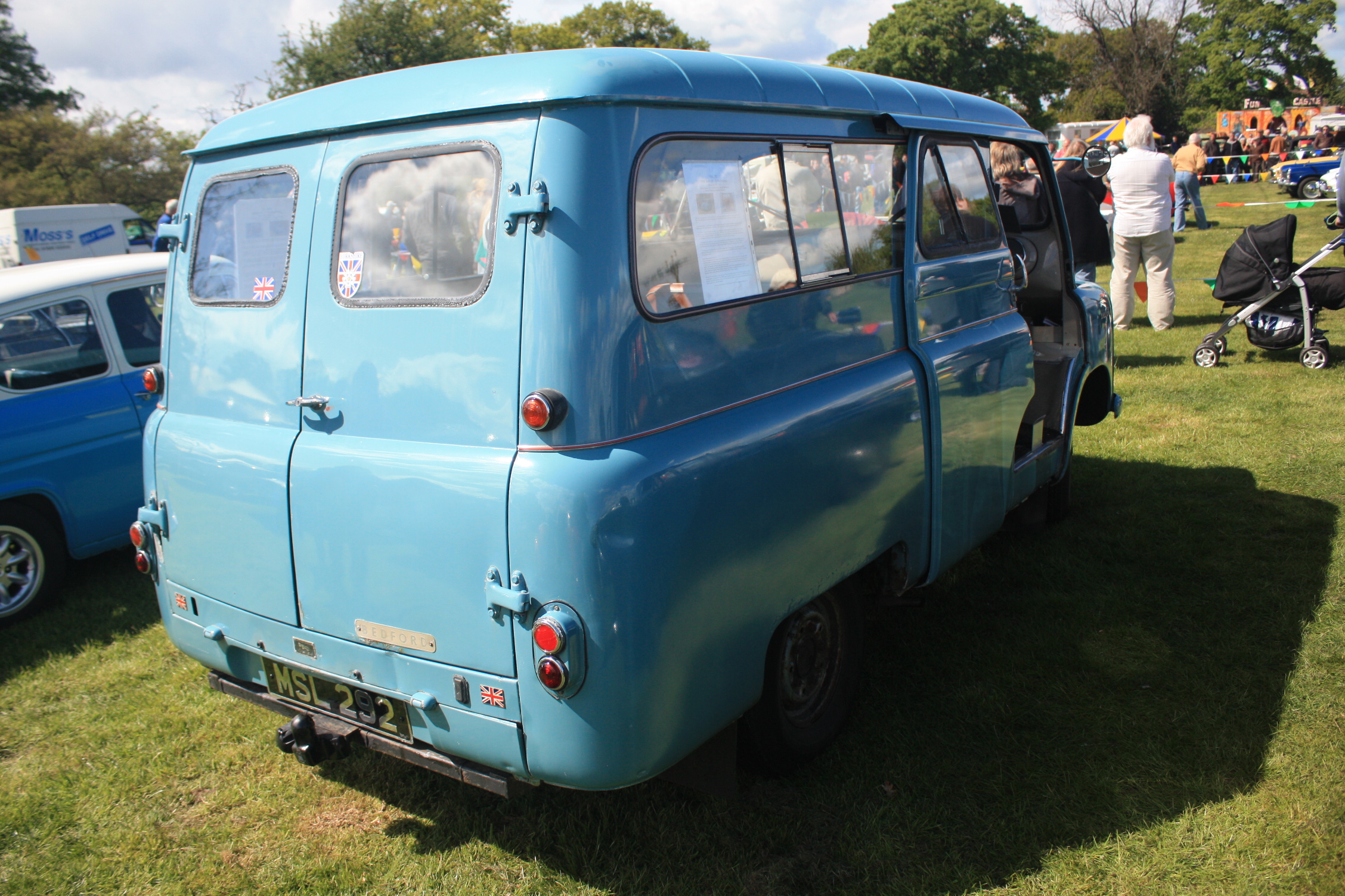
Rear view of A 1960 Bedford CA van Workobus conversion

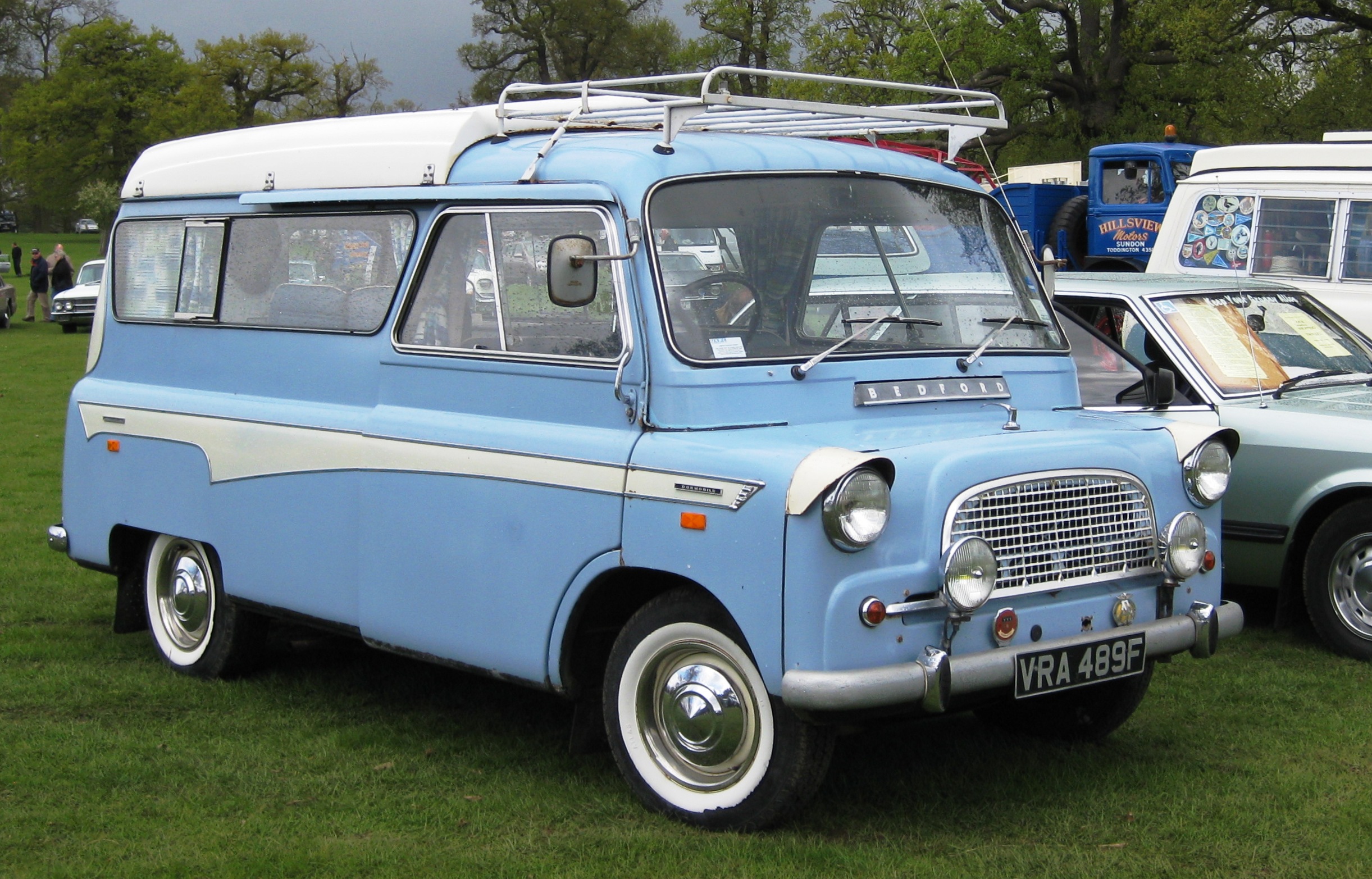
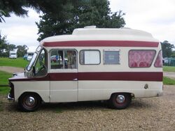
Bedford CA van based Dormobile camper

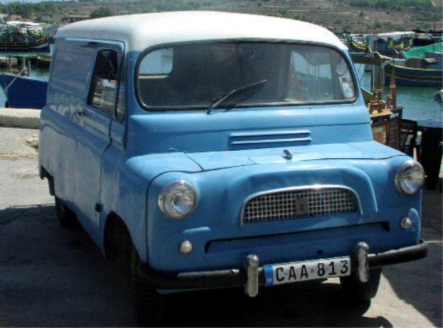
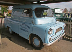
Bedford CA panel van

Bedford CA pickup

As the 1960s progressed, the Bedford CA chassis found itself used as the basis for an increasingly flamboyant succession of motor homes such as this 1965 Dormobile Debonaire. The front windscreen is shared with the standard van along with the mechanical components.
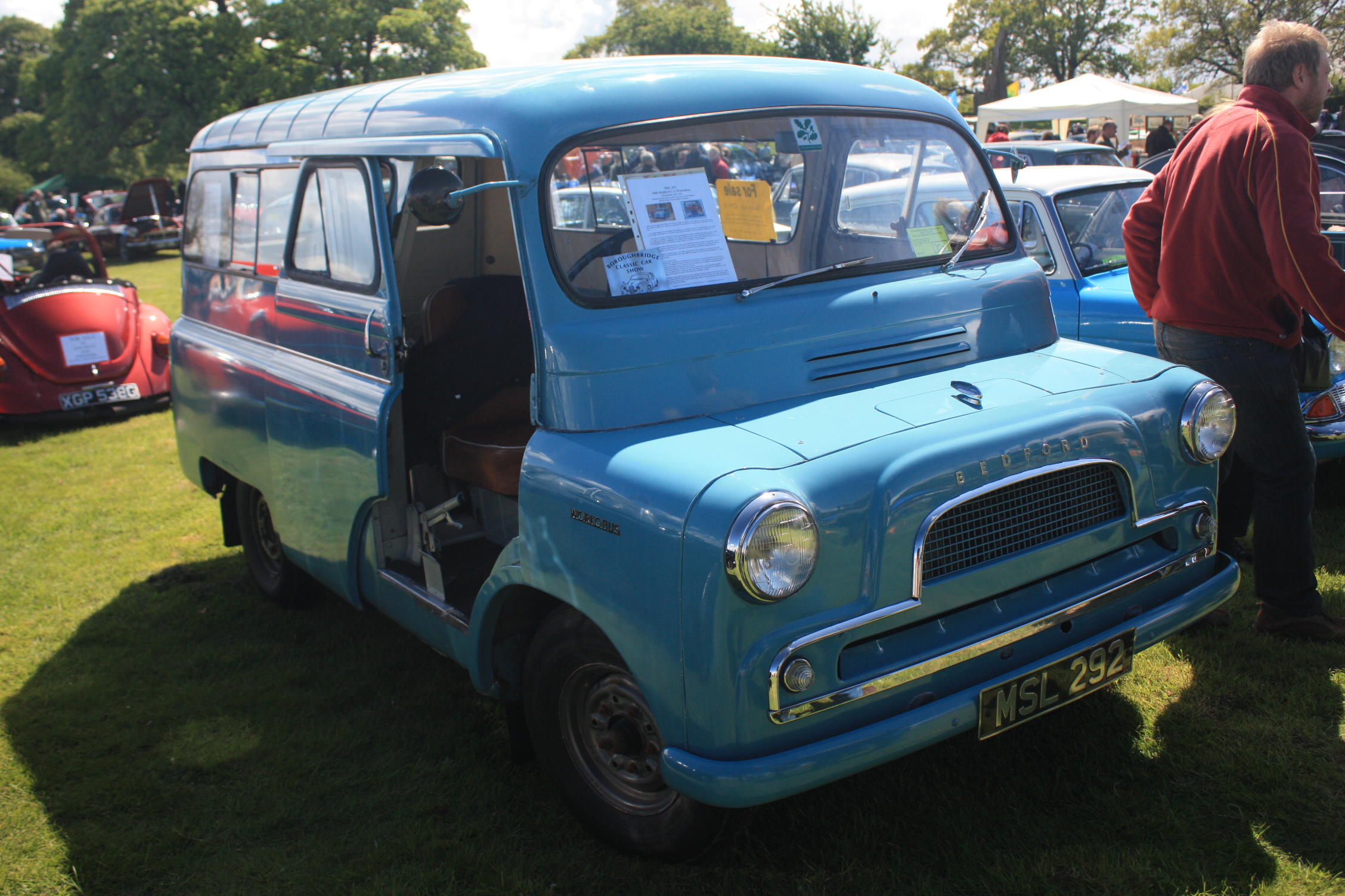
The Bedford CA was a distinctive pug-nosed light commercial vehicle produced between 1952 and 1969 by Vauxhall Motors subsidiary Bedford Vehicles, in Luton, United Kingdom.
It was manufactured in short-wheelbase and long-wheelbase forms, each form available in either a 10–12 cwt or a 15 cwt version.[1]
Generally it was supplied as a light delivery van with sliding doors, but it was also available as a chassis with cowl upon which specialist bodywork could be added.[1] The Bedford Dormobile was a Campervan conversion based on the Bedford CA van.
In its day, the vehicle was ubiquitous; the Ford Transit of its time. These vehicles are now rare.
The CA was also exported to Canada and sold as the Envoy CA, as part of the Envoy brand line-up.
Dimensions[]
| details[1] | ||
|---|---|---|
| overall width | 70.0 inches (1,778 mm) | |
| overall height (unladen) | 74.75 inches (1,899 mm) | |
| axle track | 53.25 inches (1,353 mm) (front) | 54.5 inches (1,384 mm) (rear) |
| short wheelbase | long wheelbase | |
| wheelbase | 90 inches (2,286 mm) | 102 inches (2,591 mm) |
| overall length | 154 inches (3,912 mm) | 166 inches (4,216 mm) |
| kerb weight | 2,245 pounds (1,018 kg) | 2,345 pounds (1,064 kg) |
| turning circle | 34 feet (10.4 m) | 37 feet (11.3 m) |
Body[]
The overall profile and architecture of the CA changed little during the vehicle's seventeen year life. There were, however, three distinctly different version sold. The first CAs featured a two-piece windscreen, comprising two separate flat sheets of glass separated with a central vertical metal divide. As curved screen glass became available in the UK at an acceptable price, the two piece windscreen was replaced with a single slightly curved windscreen in approximately 1958. At the same time the painted front grille of the original, which had featured a central split reflecting the split windscreen, was replaced by a smaller unsplit front grille, still painted in the van's body colour. The third version of the Bedford CA, sold from late 1964, featured a deeper windscreen and a corresponding reduction in the width of the painted metal scuttle panel directly below the windscreen. The 1964 vans also reflected general trends in car design of the time in featuring, for the first time, a pressed aluminium alloy front grill.
Powertrain[]
The CA utilised a contemporary powertrain layout. This consisted of a front-mounted longitudinally-oriented internal combustion engine, and rear-wheel drive. The transmission was mounted immediately behind the engine, and torque was transmitted to a live rear axle via a tubular prop shaft.
The engine and three-speed gearbox, were also used in the Vauxhall F-series Victor. The four-speed gearbox from later FC-series models could be easily retro-fitted to any three-speed Bedford CA, and later was offered as a factory option.
Engine[]
The vehicle was powered by an inline four cylinder petrol engineof 1508cc at first with pushrod operated overhead valves and a three-main bearing crankshaft. The fuel pump, oil pump and distributor were driven directly off the camshaft. A Zenith 34VN downdraft carburetter was fitted. The engine was available in either a low compression or a (less frequently specified) high compression version.[1] Later models also benefitted from the slightly larger 1,594 cubic centimetres (97.3 cu in) engine, as fitted in the Vauxhall Victor FB post 1964.[2] A 1622cc (99cu.in) Perkins diesel engine was also available.[3]
The engine extended back into the vehicle's passenger compartment, and was covered by a removable cowling. The vehicle thus had a very short bonnet, giving it its distinctive look. This configuration meant that the driver and passenger were travelling with their feet alongside the engine, but allowed a good proportion of the vehicle's overall length to be used for its payload. Access to the engine for routine checks was via the tiny bonnet flap, or the interior cowl. For major overhaul of the engine, the front panel containing the headlights and grille, and the chassis front crossmember had to be completely removed.[1] A popular aftermarket conversion of the time was the use of the Perkins 4/99 diesel engine. This was low on power (40 bhp) but was capable of superior fuel economy.
| details[1] | ||
|---|---|---|
| engine configuration | inline four overhead valve petrol engine | |
| engine displacement | 1,508 cubic centimetres (92.0 cu in) | |
| cylinder bore | 3.126 inches (79.4 mm) | |
| piston stroke | 3.000 inches (76.2 mm) | |
| low compression | high compression | |
| compression ratio | 6.8:1 | 7.8:1 |
| max. motive power | 52.0 bhp (38.8 kW) @ 4,000 rpm | 54.8 bhp (40.9 kW) @ 4,200 rpm |
| max. torque | 81.7 ft·lbf (111 N·m) @ 2,400 rpm | 84.5 ft·lbf (115 N·m) @ 2,400 rpm |
Transmission and final drive[]
The vehicle initially had a three-speed manual transmission driving the rear roadwheels via a semi-floating live rear axle.[1] Later models had a four speed transmission option.
Suspension and steering[]
Front suspension[]
The front suspension comprised double wishbones and coil springs atached to a front axle crossmember. An anti-roll bar linked the two lower wishbones.[1] A similar arrangement was later used on the Vauxhall Viva.
Rear suspension[]
The rear suspension comprised semi-elliptic leaf springs, 2.25 inches (57 mm) wide, mounted on the chassis and shackled to the rear axle. The 10–12 cwt version had seven leaves, and the 15-17 cwt version had eight leaves. Each leaf was 0.25 inches (6.4 mm) thick.[1]
Steering system[]
Steering was effected by a Burman recirculating ball type steering gear, a four rod linkage system and two relay levers.[1] This design is unlikely to have been precise, because of all of the linkages it involves. In practice, the system was reasonably precise, and a CA actually handled better than the early Ford Transit due to the independent front suspension.
Operating controls and instruments[]
The gear change was mounted on the steering column. The direction indicator switch was mounted in the instrument panel. The headlamp dip switch was foot operated. The starter switch was push-operated and mounted on the floor panel below the handbrake.[1]
Instruments were limited to a speedometer, a fuel gauge and a water temperature gauge.
The Bedford CA was designed in an era when semi-conductor devices were state-of-the-art, and not affordable for automotive applications. Water temperature was thus measured mechanically, via a capillary tube connected to capsule containing a volatile liquid. The capsule was screwed into the body of the water pump. Any change in temperature of the engine coolant evaporated or condensed the volatile liquid, altering the pressure on a mechanical linkage in the water temperature gauge, which moved the position of the needle. Later models used an electric gauge.
The fuel gauge was electrically controlled, as is the case in vehicles today. The sensor unit in the fuel tank could use the electrical resistance of a float-variable rheostat to measure the level of fuel, and was therefore not dependent upon the new semi-conductor technology.
Braking system[]
The braking system comprised a cast-iron detachable brake drum on each roadwheel, with the retardation provided by asbestos-lined brake shoes mounted in a leading/trailing arrangement. The shoes were operated by double-acting Lockheed hydraulic cylinders, fed by a single hydraulic circuit connected to the brake master cylinder, which was mechanically linked to the brake pedal.[1] This design was normal for that time, but had some inherent problems, and is inadequate by modern standards.
Presrvation[]
A few restored examples can be seen at UK Vintage vehicle shows.
- List known examples here
Gallery[]
please add your images here.
")
")
See also[]
- List of Commercial vehicles
- Car manufacturers
- Collector related
References[]
External links[]
- Bedford-World.com — the international owners club for all Bedford types is The Bedford Register & Drivers Club International. Special section for CA ice-cream vans.
- bedford-ca.com — information, manuals and links to parts suppliers for Bedford CA models
| |||||||||||||||||||||||
| This page uses some content from Wikipedia. The original article was at Bedford CA. The list of authors can be seen in the page history. As with Tractor & Construction Plant Wiki, the text of Wikipedia is available under the Creative Commons by Attribution License and/or GNU Free Documentation License. Please check page history for when the original article was copied to Wikia |